Radiation hazard monitors and field strength probes
Power Flux Density (PFD) probes are widely used for Health and Safety surveys to ensure personnel are not exposed to harmful levels of RF or microwave radiation, a requirement which became law for occupational exposure on 30 April 2008. Field strength probes measure the electric or magnetic field strength for near field measurements, and in applications related to Electromagnetic Compatibility (EMC) testing to IEC61000-4-3.
Three Crawford TEM cells and the NPL Tapered TEM cell are used to produce calculable electric and magnetic field strengths over the frequency range 10 Hz to 2.4 GHz. Crawford cells are, in principle, coaxial lines expanded by input and output tapers to form a rectangular outer shielding conductor with a flattened inner conductor called the septum. They are operated in the transverse electromagnetic mode, so that both the E-field and H-field components generated between the septum and outer conductor have the characteristics of a wave propagating in free space.
 The field strength can be calculated from the dimensions of the cell, its impedance at the measurement plane and the input power. TEM cells have an upper frequency limit, determined by the size of the cell, below which, the fields set up in the central region are essentially uniform which makes them ideal for calibrating probes. However, once the upper frequency limit is exceeded, higher order modes can propagate, which give rise to large spatial variations in the fields. For electrically small probes the NPL Tapered TEM cell can be used up to 2.5 GHz. The Tapered cell is equivalent to the input taper of a Crawford type cell terminated with microwave absorber. The accurately made tapered profile, ensures that almost all of the input power goes into the TEM mode, so that errors associated with higher order modes are kept to a minimum. For the highest accuracy, a large anechoic chamber is used from 250 MHz.
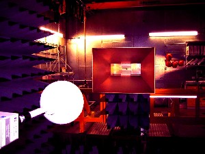
In the frequency range 250 MHz to 45.5 GHz, measurements are carried out inside an anechoic chamber, where the calculable, uniform field is generated using a calibrated coaxial or waveguide coupler system feeding a horn antenna. Knowing the power fed into the antenna and its gain, one can readily calculate the power flux density and hence field strength at a known distance from the horn antenna.
Unless otherwise specified by the customer, the calibration data are given in the form of correction factors by which the indicated reading must be multiplied to give the true value. The measurement service is UKAS Accredited for the RF calibration of field probes and dc calibration of some types of indicating meters.
Our calibration methods comply with the requirements of IEC 61000-4-3, IEEE 1309/2004 and EN50366.
Don’t see what you are looking for? Our diverse skill set enables us to provide bespoke solutions. Please contact us to discuss your requirements.
Contact us